¶ Step 1: Unboxing
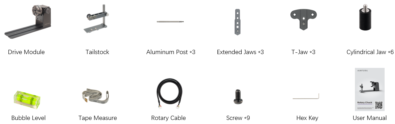
Open the package, remove the foam insert and user manual. Lift out the rotary chuck and the tailstock assembly, then remove all accessories.
Check all included accessories against the parts list below:
| No. | Name | Quantity |
|---|---|---|
| 1 | Drive Module | 1 |
| 2 | User manual | 1 |
| 3 | Tailstock | 1 |
| 4 | Aluminum Posts | 3 |
| 5 | Extended Jaws | 3 |
| 6 | T-Jaws | 3 |
| 7 | Cylindrical Jaws | 6 |
| 8 | Bubble Level | 1 |
| 9 | Tape Measure | 1 |
| 10 | Rotary Cable | 1 |
| 11 | Screws | 9 |
| 12 | Hex Key | 1 |
Tip: If any item is missing or damaged, stop installation and contact after-sales support.
¶ Step 2: Install Jaw Tips onto the Chuck
¶ 2.1 Remove the Chuck
Remove the chuck from the drive unit to prepare for jaw tip installation.
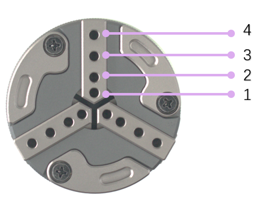
Each chuck arm features four mounting hole positions, allowing you to select the optimal position based on the workpiece diameter you need to clamp.
¶ 2.2 Extend the Chuck Arms
- Rotate the chuck adjustment ring
- Extend the three chuck arms
- Extend the curved support arms (required for larger diameter objects)
¶ 2.3 Attach the Chuck to the Drive Unit
- Align the coupling pins with the coupling slots
- Push the chuck in until you hear a "click" indicating it's locked in place
¶ 2.4 Common Combination Installation Examples
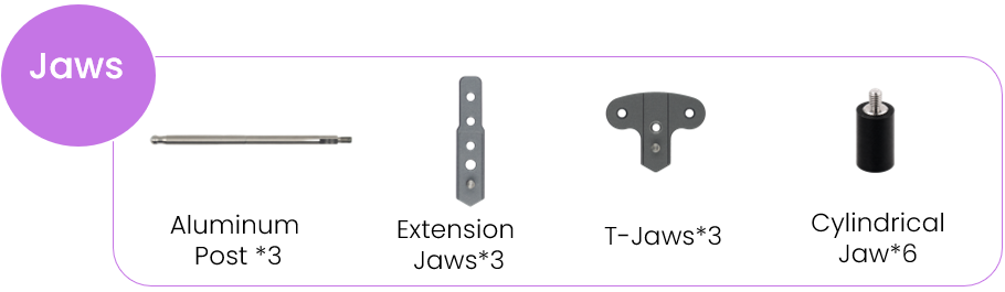
Select the appropriate jaw combination based on the type of workpiece you plan to machine.
¶ Installing Aluminum Posts (for Ring Engraving)
Install aluminum posts on all three chuck arms for internal gripping of rings and annular workpieces.
| Step | Image |
|---|---|
| Screw aluminum posts into chuck arm mounting holes | 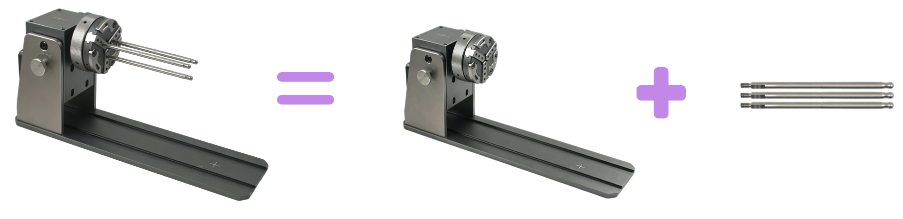 |
¶ Installing Cylindrical Jaws (for Standard Cylinders)
Install two cylindrical jaws per chuck arm for a total of six jaws. Use this configuration for external gripping of cylindrical workpieces.
| Step | Image |
|---|---|
| Install one jaw at a time until all are in place | 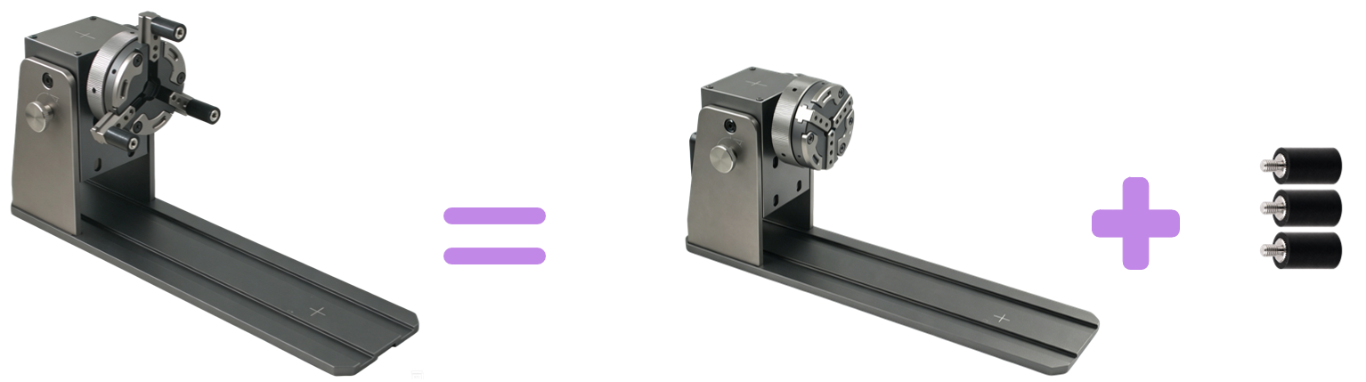 |
¶ Installing T-Jaw + Cylindrical Jaw Combination
Mixed configuration. Install both T-jaws and cylindrical jaws to accommodate mixed diameter requirements.
| Step | Image |
|---|---|
| T-Jaw + Cylindrical jaw combination | 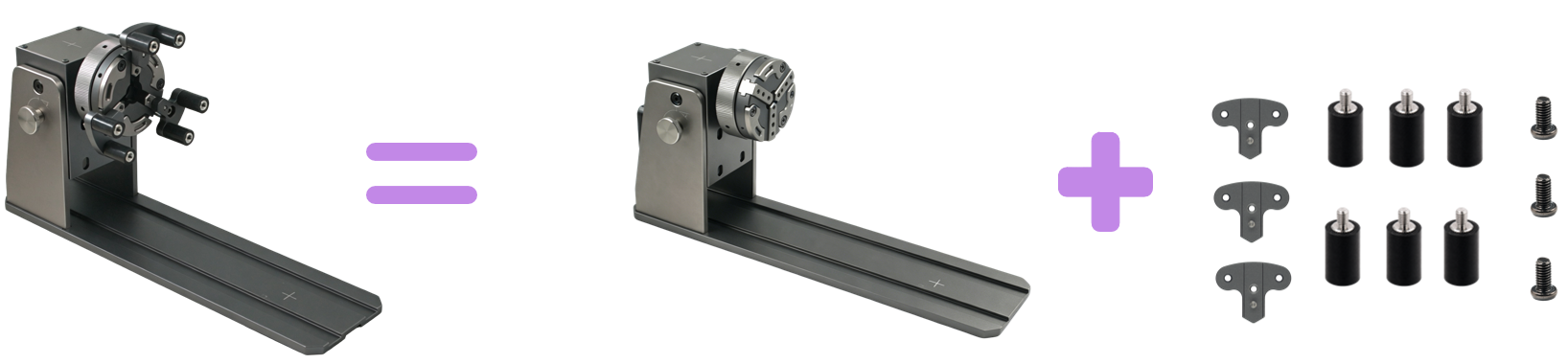 |
¶ Installing Cylindrical Jaws + Extension Arms (for Large Tumblers)
Mount cylindrical jaws on extension arms to accommodate larger diameter large-capacity tumblers.
| Step | Image |
|---|---|
| Extension arm + cylindrical jaw combination | 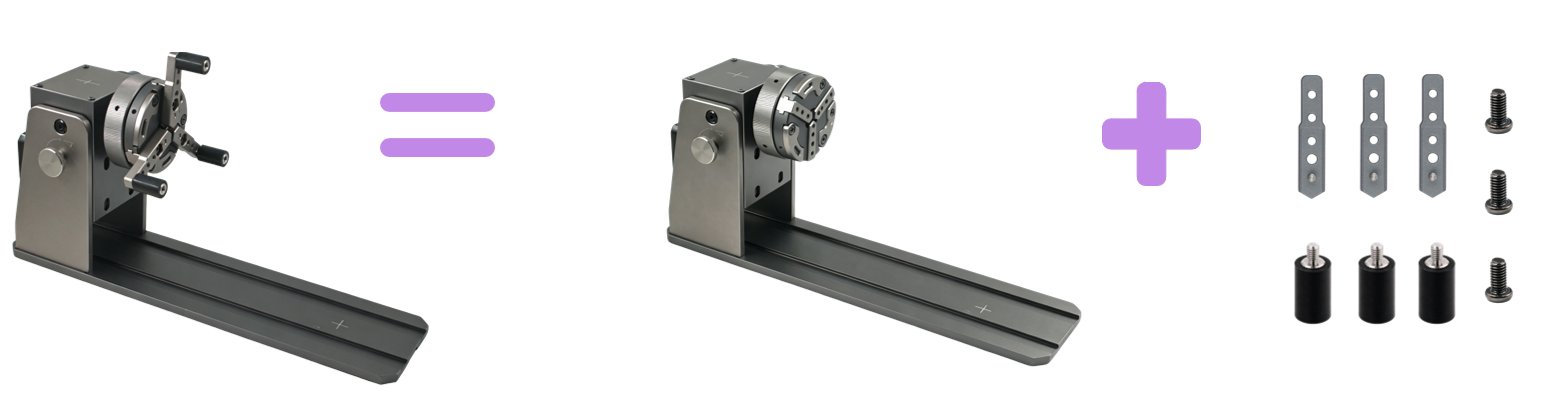 |
¶ Installing T-Jaw + Cylindrical Jaw + Extension Arms (Maximum Versatility)
The full combination achieves the widest diameter range and accommodates most workpiece types.
| Step | Image |
|---|---|
| Full combination installed | 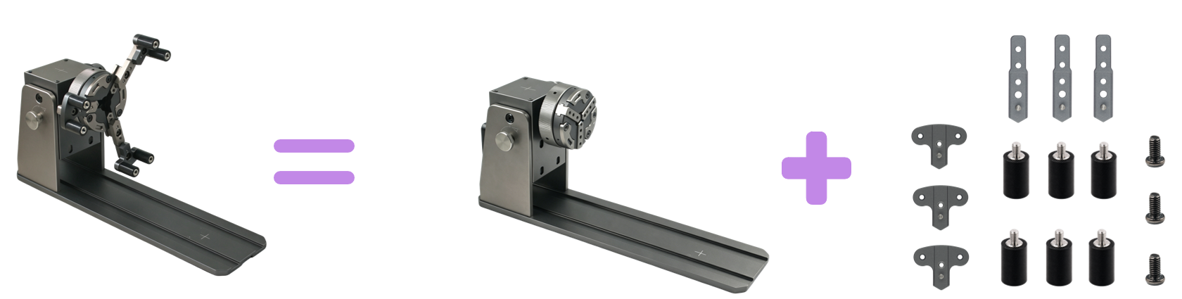 |
After installing all jaw tips, large workpiece gripping is complete. Proceed to the next step.
¶ Step 3: Install the Tailstock
- Slide the tailstock base into the rail groove
- The tailstock supports two mounting orientations — select the appropriate orientation based on workpiece length
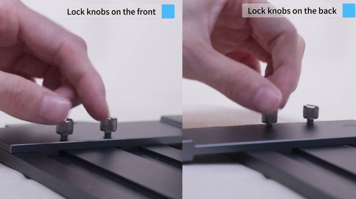
- Tighten both base lock knobs to secure the tailstock
- Adjust support arm height and roller position to align with the workpiece axis
- Tighten the height adjustment knob to lock the position
Tip: The tailstock base slides freely along the base rail to accommodate different workpiece lengths. Lock it in place once you find the optimal position.
¶ Step 4: Level with the Bubble Level
Leveling is required to keep the engraving surface flat and maintain accurate laser focus throughout the engraving process.
- Loosen the angle lock knob
- Loosen the side angle adjustment knob
- Rotate the rotary module
- Place the bubble level on top of the workpiece
- Rotate slowly until the bubble is centered
- Tighten all lock knobs
After leveling is complete, you can install the entire rotary assembly onto your laser engraver base, connect the cable, and start engraving.
¶ Five Common Jaw Configuration Reference
Five common configurations cover most workpiece types:
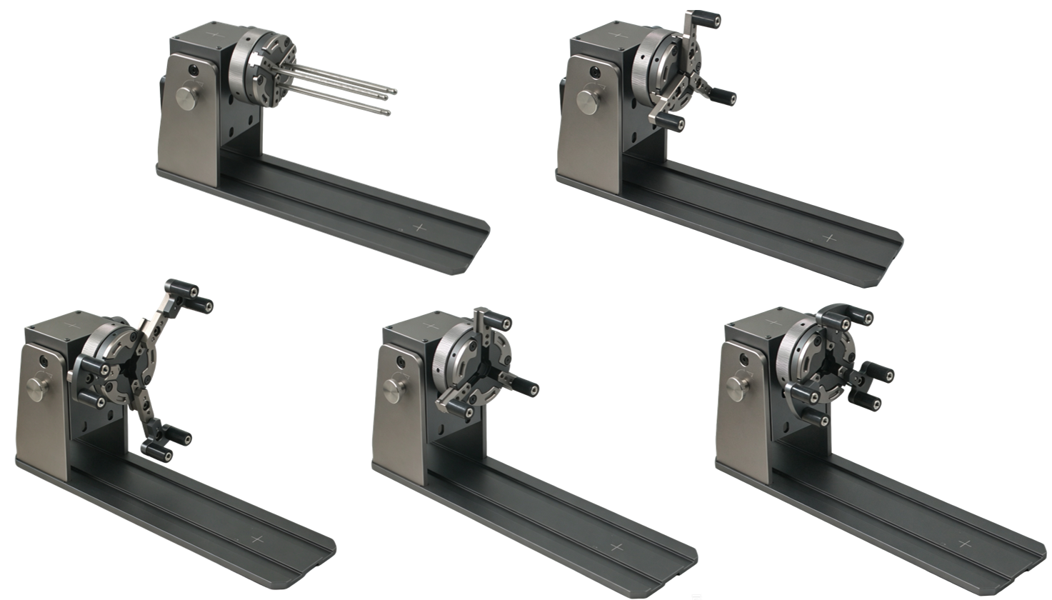
| Config | Configuration | Suitable Workpieces |
|---|---|---|
| 1 | Aluminum Posts ×3 only | Rings, annular workpieces (internal grip) |
| 2 | T-Jaws ×3 only | Medium internal diameter annular workpieces |
| 3 | T-Jaws ×3 + Cylindrical Jaws ×3 | Mixed diameter requirements |
| 4 | Cylindrical Jaws ×6 only | Standard cylinders (cups, bottles) |
| 5 | Cylindrical Jaws ×6 + Extension Arms ×3 | Large capacity tumblers (40 oz+) |