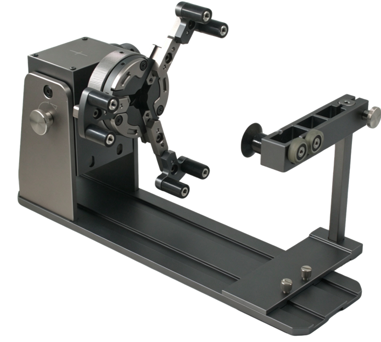
The Aliencell Rotary Chuck is a precision-engineered 3-jaw self-centering rotary attachment designed to hold and rotate cylindrical, conical, spherical, and irregularly shaped objects during laser engraving. Its modular design allows for multiple jaw configurations to accommodate workpieces of various sizes and shapes.
¶ Main Structure
The rotary chuck consists of four primary assemblies: the Drive Unit, Chuck, Tailstock, and Base Assembly.
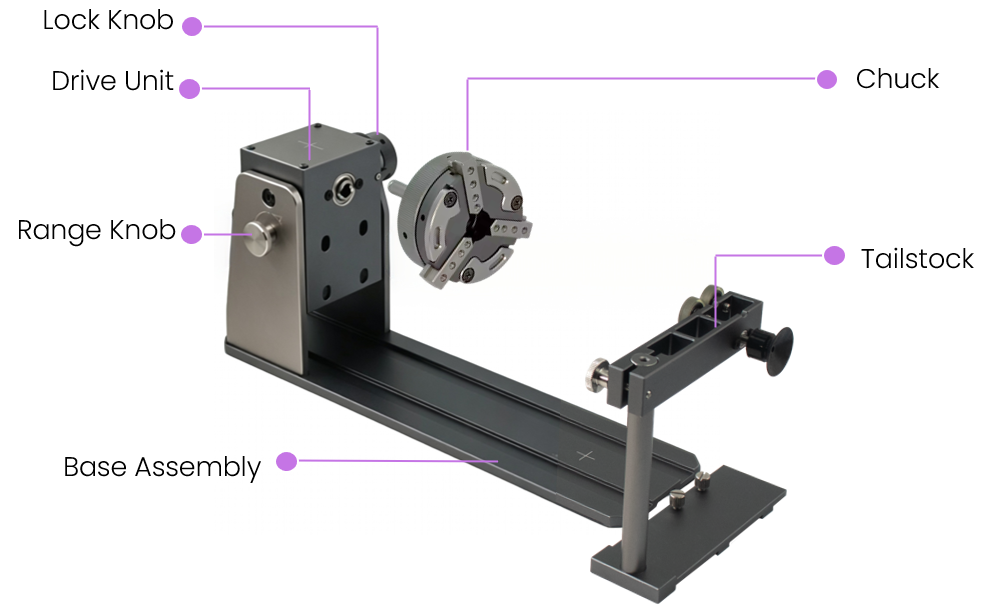
| Component | Function |
|---|---|
| Drive Unit | The motorized assembly that rotates the chuck. Contains the Lock Knob to secure the chuck position and the Range Knob to adjust the chuck arm extension. |
| Chuck | The 3-jaw self-centering clamping mechanism that holds workpieces securely during rotation. Accepts interchangeable jaw tips for different applications. |
| Tailstock | The adjustable support assembly that stabilizes the free end of long workpieces. Features height adjustment and support rollers for smooth rotation. |
| Base Assembly | The aluminum extrusion rail that provides a rigid foundation and allows the tailstock to slide horizontally for different workpiece lengths. |
¶ Chuck Structure
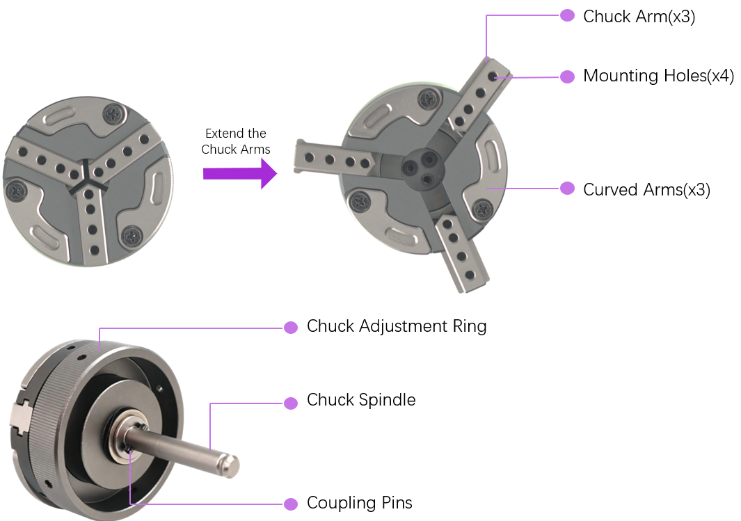
The chuck is a precision 3-jaw self-centering mechanism that expands to grip workpieces from the inside or contracts to grip from the outside.
¶ Chuck Components
| Component | Function |
|---|---|
| Chuck Arms (x3) | Three radial arms that extend outward to grip workpieces internally. Each arm features four mounting holes for jaw tip installation at different diameters. |
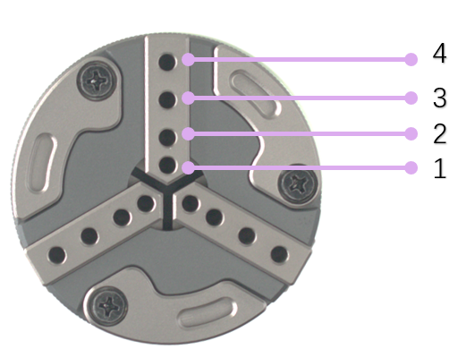
| Mounting Holes (x4 per arm) | Positioning holes along each chuck arm that allow jaw tips to be installed at different distances from the center, creating variable clamping ranges. |
| Curved Arms (x3) | Integrated curved support arms that extend outward to externally support large diameter objects. |
| Chuck Adjustment Ring | Rotating ring that extends or retracts all three chuck arms simultaneously for quick diameter adjustments. |
| Chuck Spindle | The central shaft that connects the chuck to the drive unit and transmits rotational power. |
| Coupling Pins | Alignment pins that ensure precise centering when attaching the chuck to the drive unit. Provides a secure click-lock connection. |
¶ Chuck Mounting Positions
The chuck features four mounting hole positions per arm, allowing jaw tips to be installed at different distances from the center. This design enables a wide range of clamping diameters.
¶ Tailstock Structure
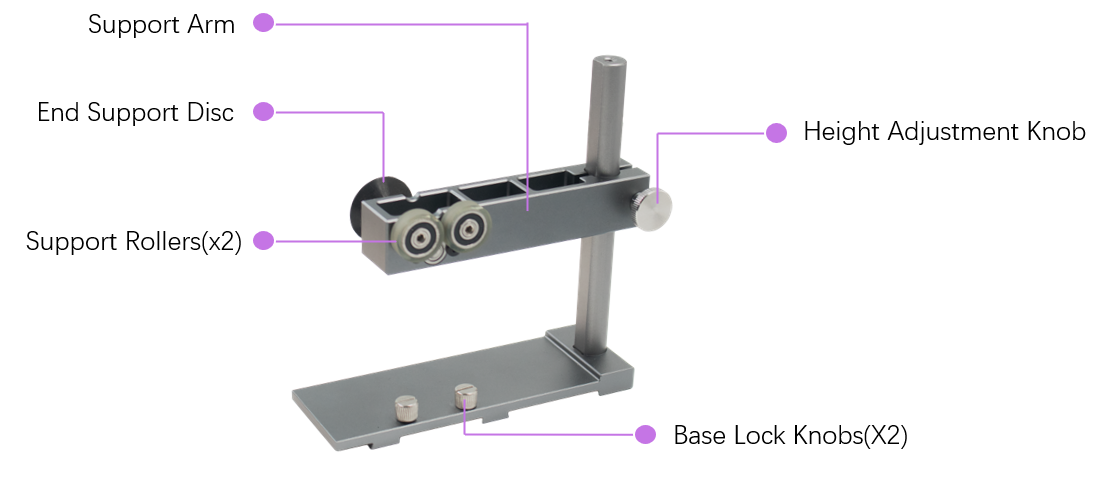
The tailstock provides critical support for long workpieces, preventing wobbling and ensuring concentric rotation during engraving.
¶ Tailstock Components
| Component | Function |
|---|---|
| Support Arm | Horizontal arm that holds the support rollers and slides vertically along the main post for height adjustment. |
| End Suction Cup | Circular suction cup that attaches to and holds the flat end of workpieces, ensuring alignment perpendicular to the rotation axis. |
| Support Rollers (x2) | Two precision rollers with rubberized surfaces that rotate with the workpiece, providing low-friction support without marking. |
| Height Adjustment Knob | Knob that locks the support arm at the desired height to match the workpiece centerline. |
| Base Lock Knobs (x2) | Two knobs that secure the tailstock base at any position along the base rail. |
Tip: The tailstock supports two mounting orientations — rotate the support arm 180° to accommodate different workpiece shapes and support requirements.
¶ Jaw Tip Types
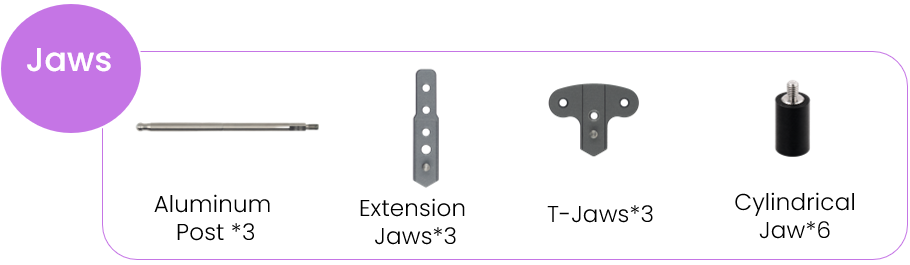
The rotary chuck includes four types of interchangeable jaw tips, each designed for specific workpiece applications.
¶ Jaw Tip Comparison
| Jaw Tip Type | Quantity | Primary Application | Ideal Workpiece |
|---|---|---|---|
| Cylindrical Jaw | 6 | General-purpose external clamping | Cylindrical objects: tumblers, bottles, pipes (5–143 mm diameter) |
| T-Shaped Jaw | 3 | Internal clamping for rings and annular objects | Rings, bracelets, hollow cylinders |
| Extended Jaw | 3 | Extended reach for large diameter objects | Large tumblers, wide vases, big cylinders |
| Aluminum Post | 3 | Internal support for ring-shaped workpieces | Rings, annular objects, small hollow items |
¶ Jaw Clamping Ranges
The modular jaw system supports multiple installation combinations to achieve the optimal clamping range for different workpiece sizes.
¶ T-Jaw Clamping Ranges (without Extension)
| Configuration | Image | Clamping Range (Internal) |
|---|---|---|
| T-Jaw at Hole 1 (closest to center) | 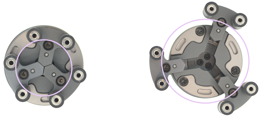 |
Ø 40 – 68 mm (1.57 – 2.68 in) |
| T-Jaw at Hole 3 (furthest from center) | 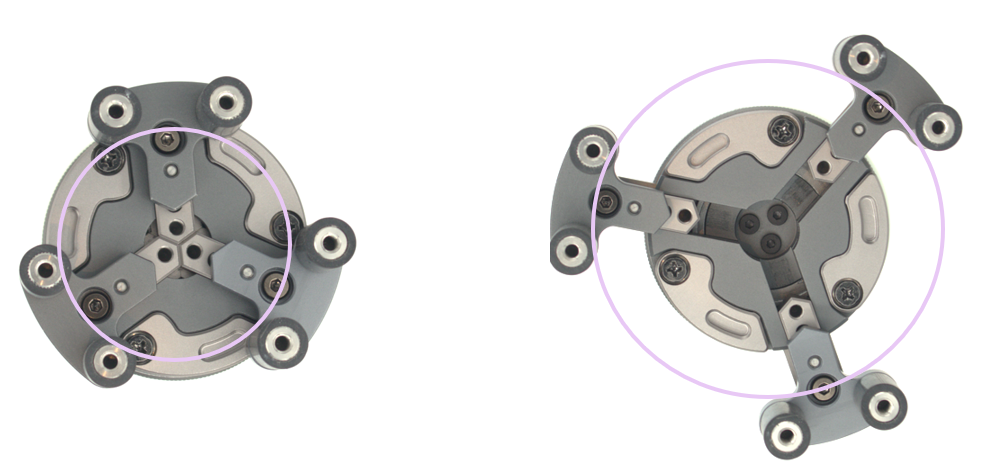 |
Ø 55 – 80 mm (2.17 – 3.15 in) |
¶ T-Jaw with Extension Arm
| Configuration | Image | Clamping Range (Internal) |
|---|---|---|
| Extension + T-Jaw at Hole 1 | 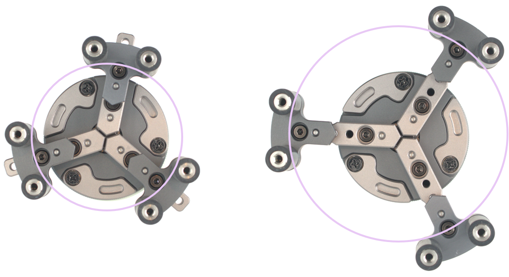 |
Ø 64 – 128 mm (2.52 – 5.04 in) |
| Extension + T-Jaw at Hole 3 | 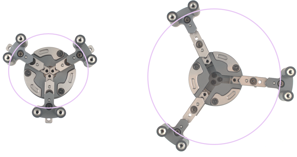 |
Ø 78 – 143 mm (3.07 – 5.63 in) |
¶ Cylindrical Jaw Clamping Ranges (without Extension)
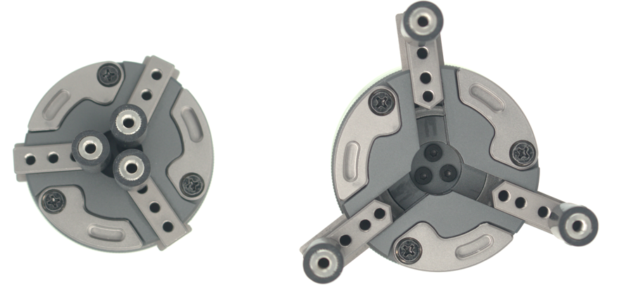
| Configuration | Clamping Range (External) |
|---|---|
| Cylindrical Jaw at Hole 1 | Ø 4 – 58 mm (0.16 – 2.28 in) |
| Cylindrical Jaw at Hole 2 | Ø 8 – 68 mm (0.31 – 2.68 in) |
| Cylindrical Jaw at Hole 3 | Ø 29 – 83 mm (1.14 – 3.27 in) |
| Cylindrical Jaw at Hole 4 | Ø 44 – 97 mm (1.73 – 3.82 in) |
¶ Cylindrical Jaw with Extension Arm
| Configuration | Image | Clamping Range (External) |
|---|---|---|
| Extension + Cylindrical Jaw at Hole 1 | 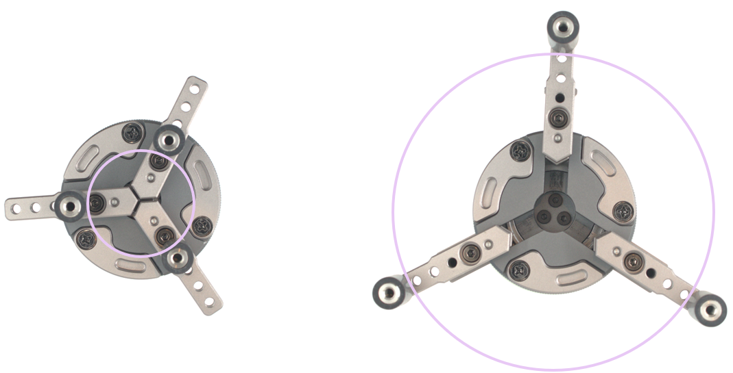 |
Ø 38 – 112 mm (1.50 – 4.41 in) |
| Extension + Cylindrical Jaw at Hole 3 | 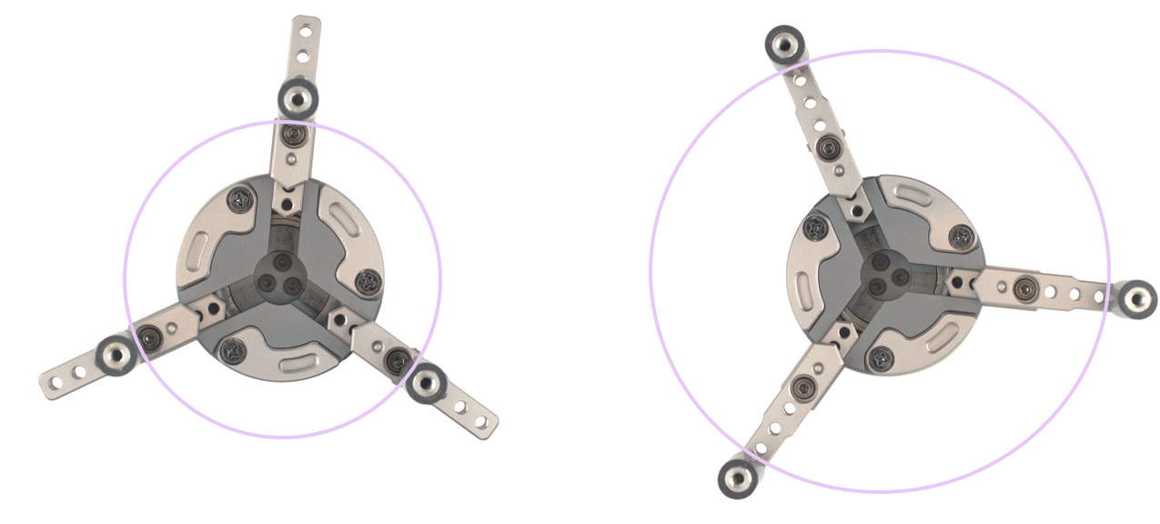 |
Ø 54 – 130 mm (2.13 – 5.12 in) |
¶ Installation Examples
The rotary chuck supports multiple installation orientations on the laser engraver base. These flexible mounting options accommodate different workpiece shapes and engraving scenarios.
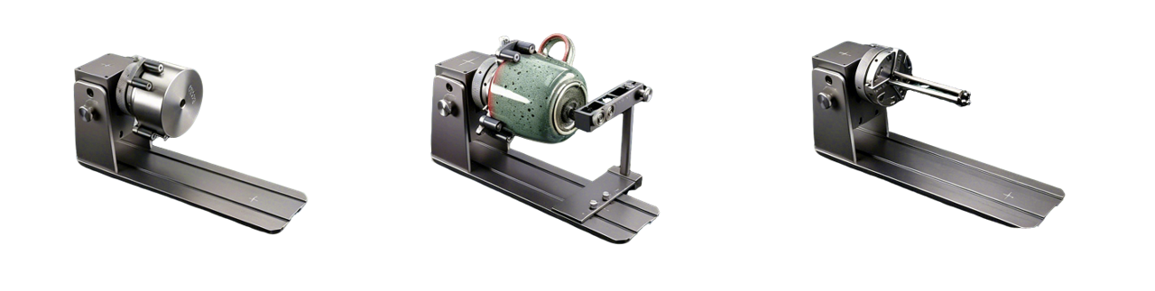
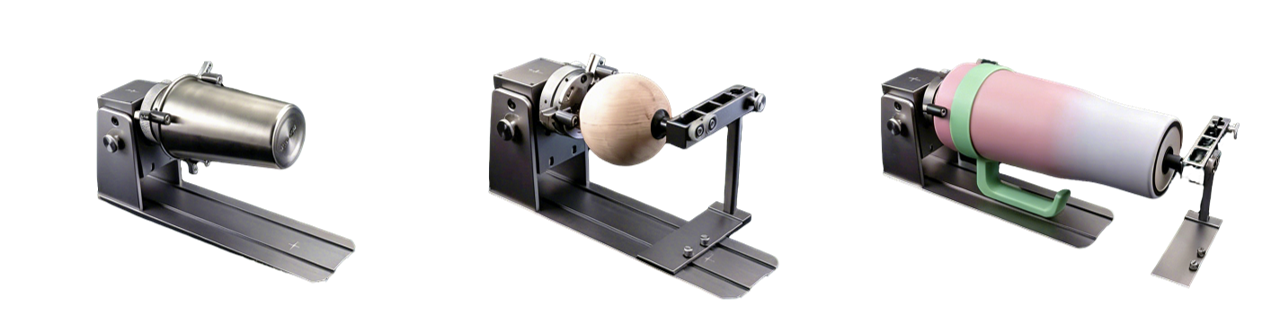
Note: Select the mounting orientation that positions your workpiece within the laser engraving area while ensuring sufficient clearance for full 360° rotation.