¶ 1. Symptoms
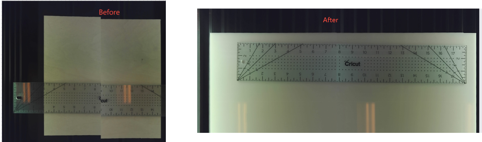
When using the Photo Positioning feature, if the real-world image displayed on the canvas does not fully match the actual position of the material, you may observe one or more of the following:
-
The live image on the canvas appears slightly shifted vertically or horizontally
-
Material edges appear overlapped or misaligned in the image
-
The crosshair position shown on the canvas does not correspond to the actual position on the material
-
The design appears correctly aligned with the material in the software, but the actual processing result is offset
These observations typically indicate that the captured image is not fully aligned with the device’s internal coordinate system, which can affect the accuracy of photo positioning.
¶ 2. How to Troubleshoot
¶ 2.1 Check the Machine Setup
The camera is designed to capture the work area within a specific working height and camera capture range.
If the machine or workpiece is raised below the standard working height, the distance between the camera and the work surface changes. This may cause image distortion or camera positioning deviation.
¶ Standard Setup Test
Before performing camera calibration, restore the machine to the standard setup:
- Switch to the laser slats or Honeycomb Panel Mode.
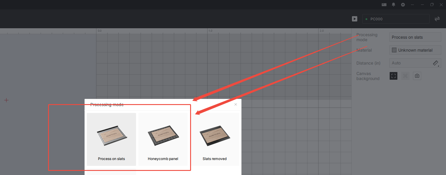
- Place a 3 mm wooden board on the laser slat or honeycmb panel.
- Capture the camera image again.
- Check whether the captured image is aligned correctly.
Note: If the camera works normally under the standard setup, the issue is likely related to the workpiece height or machine setup, rather than the camera itself.
Related Post: https://wiki.aliencell.com/en/x1_series/material_thickness_specification
¶ Common Example: Hat Engraving
When engraving hats with a custom jig, removing the tray may cause the hat to sit too low relative to the standard working height.
To improve camera positioning:
- Remove the tray.
- Raise the hat jig using blocks or another suitable support.
- Adjust the height so that the hat surface is approximately level with the Honeycomb Bed or Slat Bed.
- Capture the camera image again and check the positioning accuracy.
Trouble-shooting video:
https://youtu.be/11qwIXbTEAQ?si=kJeYNNpYXoT2G0Qf
If the image is still misaligned, continue with the troubleshooting steps below.
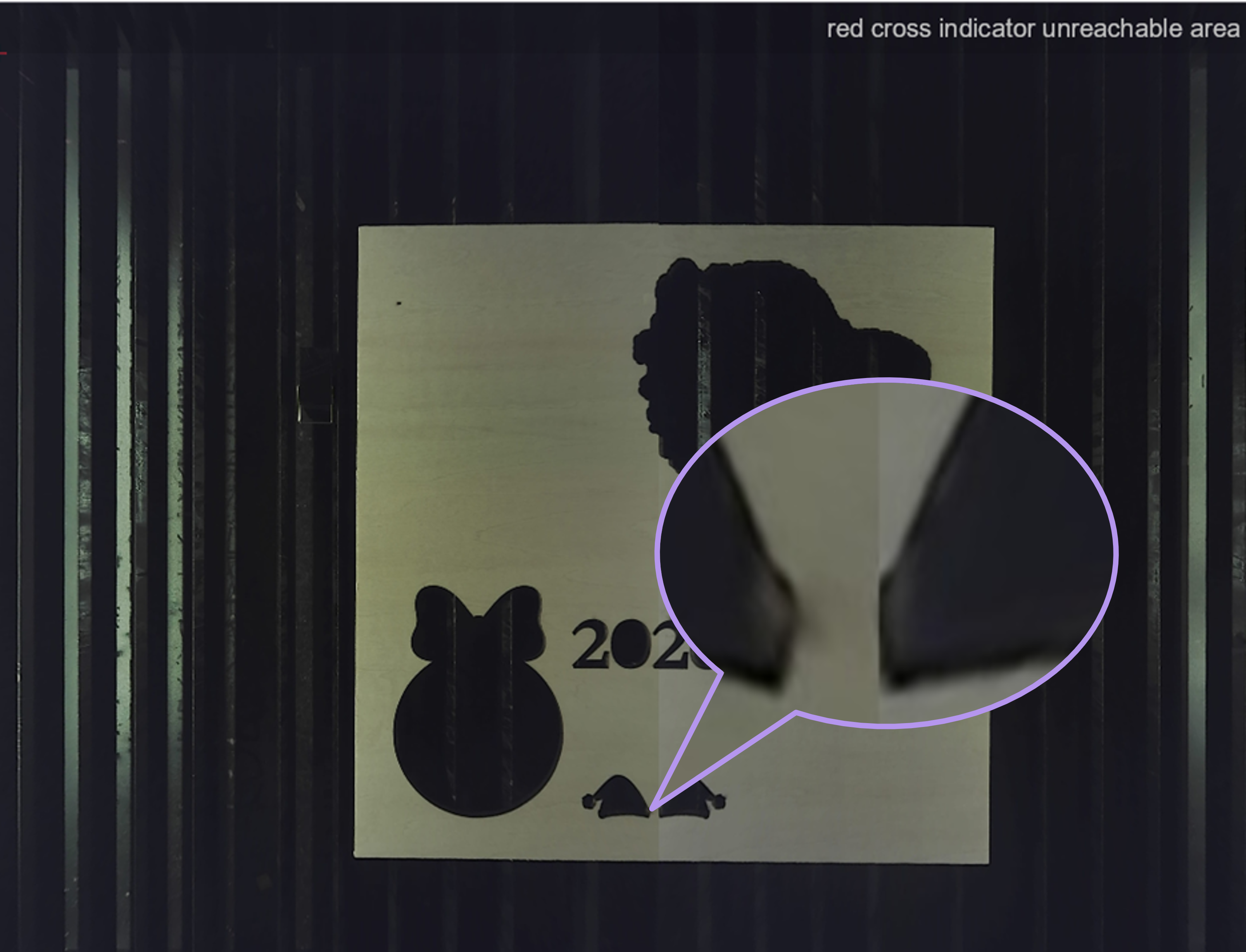
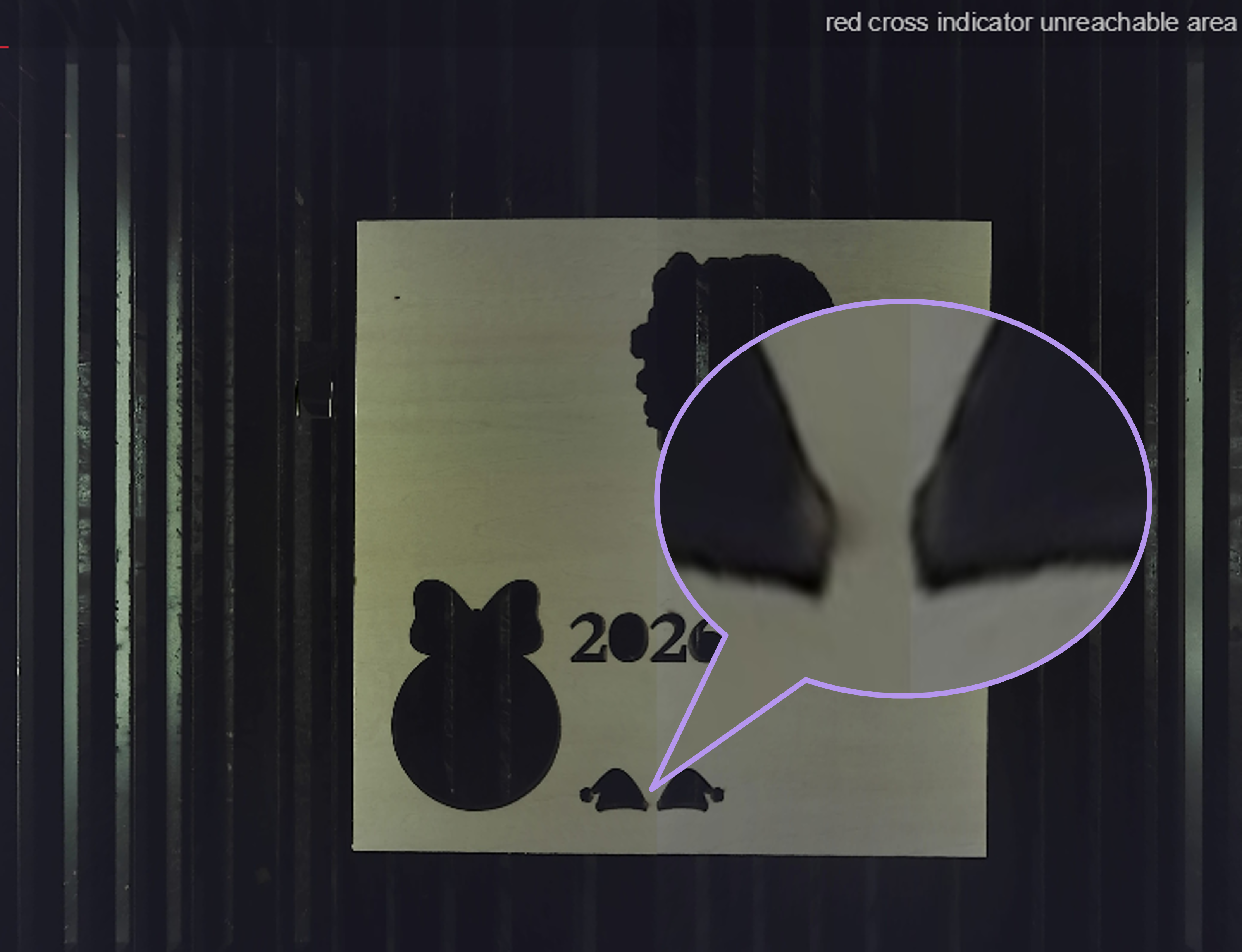
¶ 2.2 Re-measure Material Height Using “Select Point Measurement”
 |
 |
|---|---|
| Before Calibration | After Calibration |
-
Steps:
- In Aliencell Space, click the Measure
 icon and select [Measure by select point] from the dropdown menu. The cursor will turn into a red crosshair within the canvas.
 - Move the red crosshair to a location on the material surface and click to confirm. The device will automatically detect the precise height of that point and calibrate the camera view.
- In Aliencell Space, click the Measure
¶ 2.3 Take a New Photo
Sometimes lighting or angle can momentarily affect the capture. Retaking the photo often resolves minor distortions.
¶ 2.4 Perform Photo Capture Calibration
If you carefully completed Step 2 but the image still shows noticeable offset or misalignment, the camera’s physical position may have shifted slightly from its original factory alignment. In this case, perform a full calibration on the machine’s touchscreen.
¶ Why this step is needed
The camera is mounted on the machine’s lid. Frequent opening/closing or vibration during transport can cause the camera to shift by a fraction of a millimeter.
Even this tiny displacement is enough to cause visible misalignment.The calibration process lets the camera “look at” the six alignment markers on the bottom plate again and re-establish its correct reference position.
¶ Steps:
-
Clear the work area:
Remove all materials so the six circular calibration markers on the bottom plate are fully visible and unobstructed.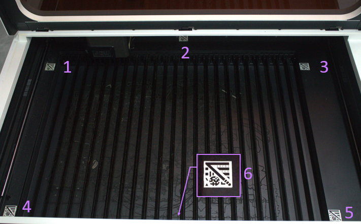
-
Open the Maintenance Menu:
On the touchscreen home page, tap Setting > Maintenance. -
Start the Calibration Program:
Tap Photo Capture Calibration.
-
Begin Calibration:
When prompted, make sure the bottom markers are not blocked, then tap Start Calibration. -
The system will automatically:
-
Home — The laser module moves to a predefined location to clear the camera’s view
-
Capture images — The camera photographs all six calibration markers
-
Correct coordinates — The system recalculates and updates the camera alignment parameters
-
-
Finish:
After the screen shows a success message, exit the menu.
Your next camera capture will use the newly calibrated parameters.
¶ 2.5 Check the Positioning Deviation
After calibration, check the actual positioning deviation.
The X1 camera positioning accuracy is approximately ±2 mm.
- If the deviation is within 2 mm, the camera calibration is considered acceptable.
- If the deviation is greater than 2 mm, automatic calibration may not be sufficient. Manual camera calibration is required. Please send a photo to support@aliencell.com for further analysis.