¶ 1. Driver Board Interface Details
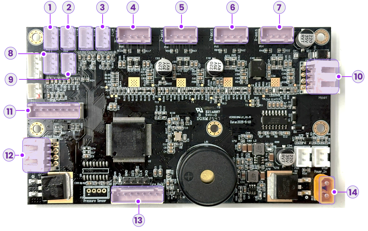
No. |
Port Function |
Cable Label |
|---|---|---|
| 1 | X-Axis Limit Switch Port |  |
| 2 | Y-Axis Limit Switch Port |  |
| 3 | Z-Axis Limit Switch Port |  |
| 4 | R-Axis Motor Port |  |
| 5 | Z-Axis Motor Port |  |
| 6 | Y-Axis Motor Port |  |
| 7 | X-Axis Motor Port |  |
| 8 | Base Plate Detection Port |  |
| 9 | Tray Detection Port |  |
| 10 | Host Interface | - |
| 11 | Flame Sensor Port 2 (Front) |  |
| 12 | Laser Driver Port | - |
| 13 | Flame Sensor Port 1 (Inner) |  |
| 14 | 24V DC Power Input | - |
¶ 2. Replacement Steps
¶ 2.1 Power Off and Disconnect
a. Turn off the power switch. |
b. Disconnect the air tube and power cable. |
¶ 2.2 Open the Side Access Panel
- Move the laser module to the front of the device to create workspace.
- Push the side access panel outwards from the inside to open it.
¶ 2.3 Remove Red Glue
Apply alcohol to the red glue on connectors using a cotton swab to soften it. |
Use tweezers to gently peel off the softened glue from each connector. |
¶ 2.4 Disconnect Cables
We strongly recommend taking a photo of the current wiring connections before disconnecting any cables. This will serve as a reference for reinstallation.
Disconnect the Laser Driver cable. |
Disconnect the Host Interface cable. |
-
Disconnect the yellow Power Cable and the two rows of Flame Sensor cables at the bottom.
-
Disconnect the X/Y/Z/R Axis Motor cables.
-
Disconnect the Tray Detection and Base Plate Detection cables.
-
Disconnect the Y/Z Axis Limit Switch cables.
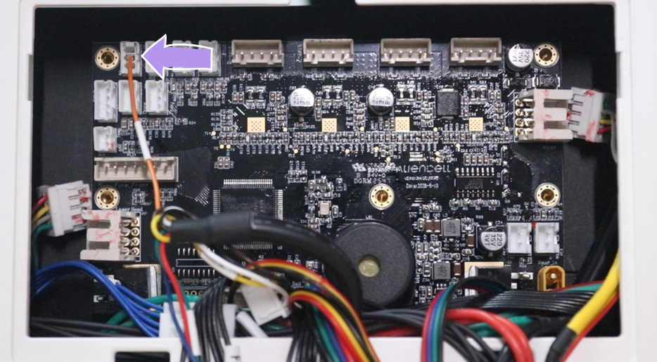
Do not pull the top-left X-Axis Limit Switch cable directly. This connector has a fragile single-wire connection and breaks easily. We recommend fully detaching the driver board from the chassis first, then carefully disconnecting this cable.
¶ 2.5 Remove the Old Driver Board
- Use a 2.0mm Hex Key to remove the 5 screws securing the motor driver board.
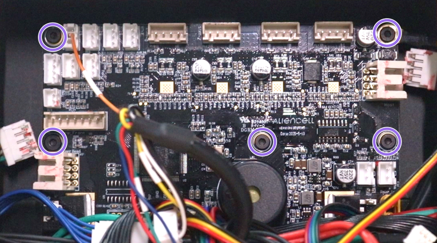
When removing the top-right screw, be sure to release and remove the Ground Wire (Yellow/Black cable).
- The driver board is secured with strong adhesive backing. After removing all screws, hold the edges of the board and pull firmly to detach it.
Be careful of sharp edges and solder points when pulling out the board to avoid injuring your hands.
¶ 2.6 Install the New Driver Board
- Tip: For easier installation, connect the Laser Driver cable and Host Interface cable before securing the board to the chassis.
- Align the board and press it against the chassis to engage the adhesive backing. Reinstall the 5 screws.
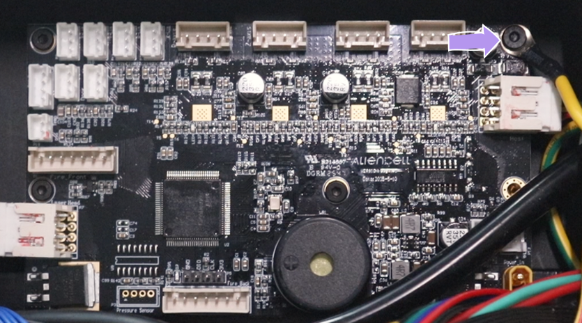
When tightening the top-right screw, ensure the Yellow Ground Wire is reattached securely.
¶ 2.7 Reconnect Cables
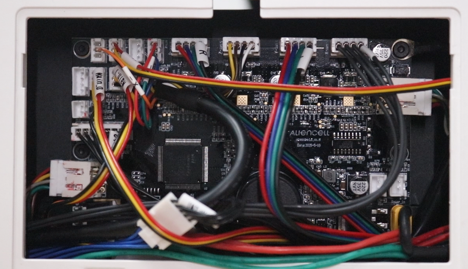
- Reconnect the remaining cables in the following order: Power Cable, Flame Sensors, Axis Motor Cables (X/Y/Z/R), Limit Switch Cables (X/Y/Z), Tray Detection, and Base Plate Detection.
- Once all connections are secure, organize the cable harness and reinstall the side access panel.