¶ 1. Distance Sensor (Probe) Replacement & Calibration Guide
¶ 1.1 Preparation
Before starting, ensure you have the following ready:
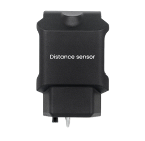
- A new distance sensor.
¶ 1.1.1 Copying the File to a USB Drive
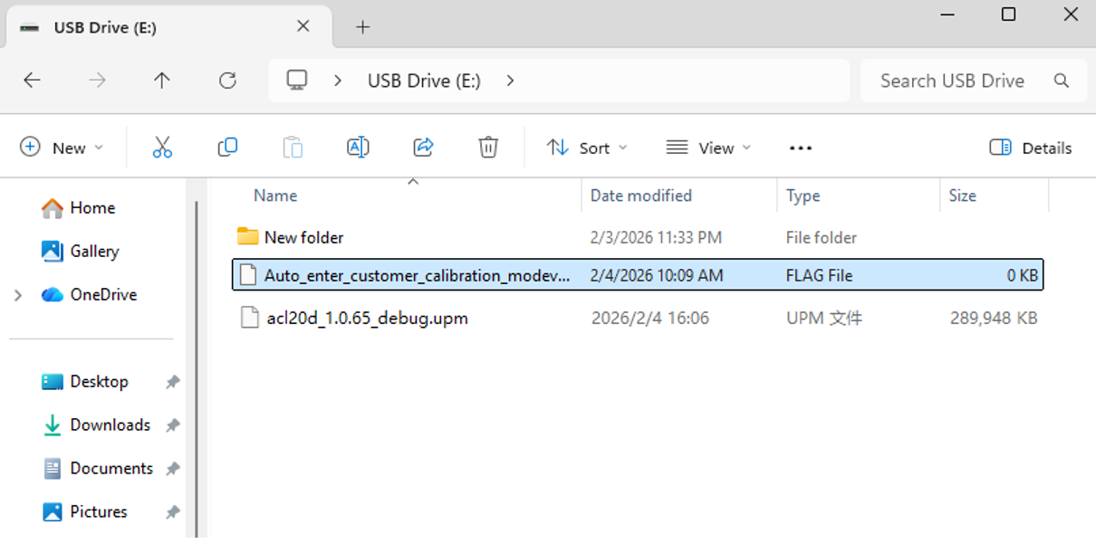
- Prepare a USB drive and copy the following file to its root directory:
- Calibration script file:Auto_enter_customer_calibration_modev1.0.flag
- Calibration script file:Auto_enter_customer_calibration_modev1.0.flag
¶ 1.1.2 Firmware Update
-
Update the machine's firmware to version 1.0.65 or later.
-
How to update: Please refer to the Local Firmware Update (Offline Update) section in our Wiki.
¶ Step 1: Manual Probe Release & Installation
Before calibration, the probe pin must be in the extended position.
- Locate the spring latch on the side of the Distance Sensor.
- Gently press the latch; the probe pin will pop out (extend).
- Install the new Distance Sensor onto the laser module.
¶ Step 2: Position the Laser Module
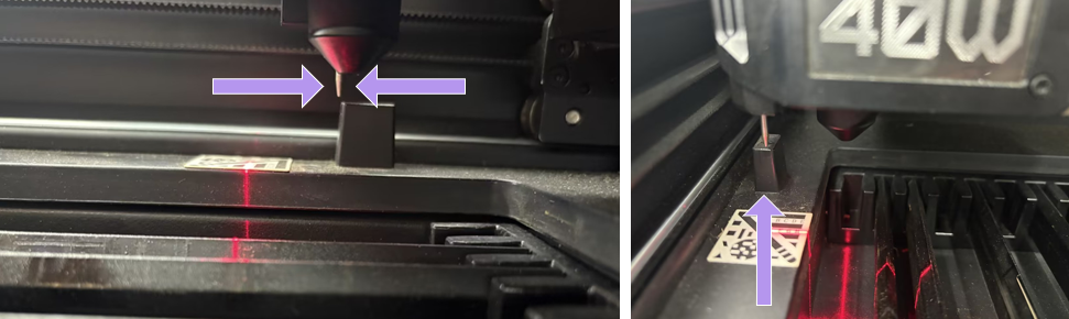
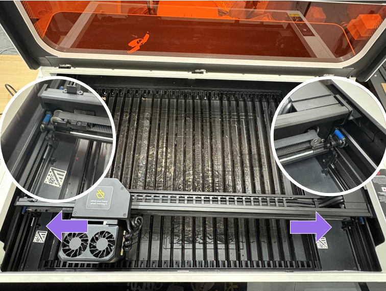
- Manually move the laser module (X-axis) toward the retraction station (top-left corner).
- Crucial Alignment: Do not push the module all the way against the frame. Position the probe pin approximately 1mm to 2mm in front of the retraction station fixed block.
¶ Step 3: Enter Calibration Mode
-
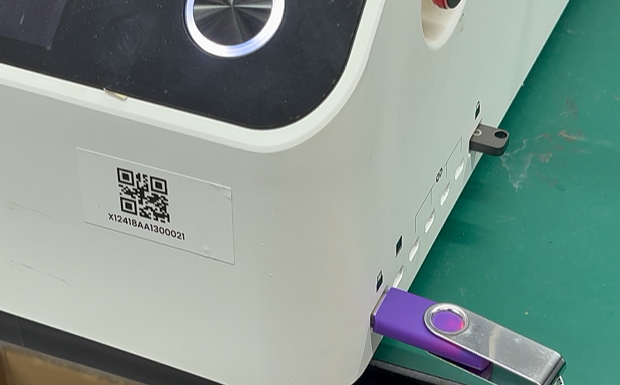
Insert the USB drive into the machine’s USB port.
-
The touchscreen will automatically detect the file and jump to the Calibration Mode interface.
¶ Step 4: Execute Laser Probe Calibration
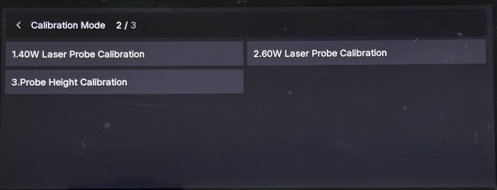
- Select the button matching your current laser module power (e.g., tap “1. 40W Laser Probe Calibration”).
- Process: The machine will move automatically. The probe will retract (by touching the retraction station) and then extend again to record position data.
- Result: Once completed, the screen will show a success indicator and return to the main calibration menu.
¶ Step 5: Execute Probe Height Calibration
- Select the option “3. Probe Height Calibration”.
- Process: The laser module will move forward to a flat area. The probe will extend to touch the surface, measure the height, and retract. This action will repeat 3 times.
- Result: Wait for the entire sequence to finish. The laser module will return to the origin, and the screen will return to the main menu.
¶ Step 6: Exit and Restart
- Tap the “Back” (<) button in the top-left corner to exit the calibration interface.
- Important: Power off the machine and restart it. This ensures all new calibration data is saved and applied correctly.
¶ 2. Probe Unable to Extend
Scenario: The probe does not extend automatically during operation or auto-focus.
¶ Phase 1: Check X-Axis Alignment (Primary Solution)
Before attempting software calibration, you must ensure the X-axis gantry is mechanically aligned. If the gantry is skewed, the probe cannot properly engage the trigger block at the retraction station.
Steps1: Check for Misalignment
- Manually move the X-axis. If the gantry is crooked, the probe mechanism at the top-left corner will not trigger correctly.
Steps2: Level the X-axis Gantry
- Pull the X-axis gantry all the way to the front of the machine.
- Check if both the left and right sides of the gantry touch the Y-axis limiters simultaneously.
- Action: If one side touches but the other has a gap, pull the gantry firmly until both sides are flush and aligned against the limiters.
Steps3: Retest
- Try the auto-focus function again. If the probe works, the issue is resolved. If the probe still does not extend, proceed to Phase 2.
¶ Phase 2: Probe Height Calibration
If mechanical alignment does not resolve the issue, please perform a probe height calibration.
-
Prepare a USB drive and copy the following file to its root directory:
- Calibration script file: Auto_enter_customer_calibration_modev1.0.flag
- Calibration script file: Auto_enter_customer_calibration_modev1.0.flag
-
Update the machine's firmware to version 1.0.65 or later.
-
How to update: Please refer to the Local Firmware Update (Offline Update) section in our Wiki.
¶ Steps
-
Manual Probe Release: Locate the spring latch on the side of the Distance Sensor.
- Press the latch to manually pop the probe out.
- Press the latch to manually pop the probe out.
-
Position the Module: Manually move the laser module to the retraction station (top-left).
- Manually move the laser module (X-axis) toward the retraction station (top-left corner).
- Crucial Alignment: Do not push the module all the way against the frame. Position the probe pin approximately 1mm to 2mm in front of the retraction station fixed block.
- Manually move the laser module (X-axis) toward the retraction station (top-left corner).
-
Enter Calibration Mode: Insert the USB drive.
-
Insert the USB drive into the machine’s USB port.
-
The touchscreen will automatically detect the file and jump to the Calibration Mode interface.
-
-
Execute Height Calibration: Select “3. Probe Height Calibration”.
- Process: The module will move forward, probe the bed, and retract. This will repeat 3 times.
- Result: Wait for the module to return to the origin.
-
Exit and Restart: Tap the “Back” (<) button to exit.
- Important: Power off and restart the machine to save the new settings.
- Important: Power off and restart the machine to save the new settings.