The toolbar is located at the bottom of the main window and provides quick access to all core tools for creating, drawing, and adding content to your canvas.

¶ 1. Import
Click the  icon in the bottom toolbar to import a variety of common image and vector formats.
- Supported formats include: PNG, JPEG, JPG, BMP, SVG, DXF
- After importing, the asset will appear on the canvas, where you can move, scale, rotate, or edit it.
¶ 2. Selection Tool
The selection tool is the primary way to interact with objects on your canvas. Clicking this icon opens a menu with two modes.
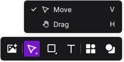
- Move: This is the default arrow tool for selecting, moving, scaling, and rotating objects on the canvas. You can click a single object or drag to select multiple objects at once.
- Pan: Represented by a hand icon, this tool lets you move the canvas view. Click and drag anywhere on an empty area to pan your workspace without accidentally shifting your design elements.
¶ 3. Shape Tools
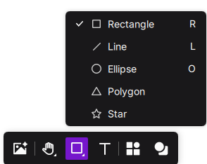
Click the  icon to expand the shape menu and quickly draw a variety of basic shapes.
¶ 3.1 Drawing Shapes
You can draw the following shapes:
- Rectangle: The default shape, used to draw squares and rectangles.
- Line: Draw straight lines.
- Ellipse: Draw circles and ellipses.
- Polygon: Create polygons with a customizable number of sides.
- Star: Draw stars, including adjustable star points.
¶ 3.2 Editing Polygons
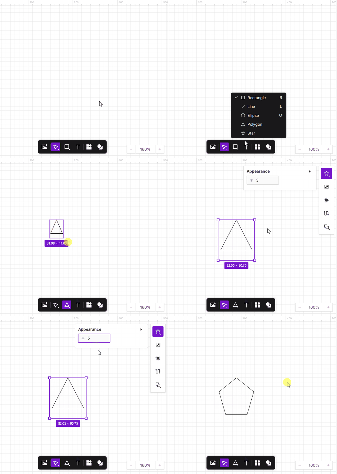
When you select a polygon on the canvas, the Style panel appears in the right properties section, allowing you to adjust the number of sides.
How to use:
- Enter any value (≥3) in the input field to generate the corresponding polygon in real time.
- You can switch freely between triangles and multi-sided polygons, making it easy to create structural shapes.
¶ 3.3 Drawing Star Shapes
The Star tool is designed for creating versatile geometric forms, ranging from standard five-pointed stars to complex multi-pointed radial patterns. Upon selecting a star on the canvas, you can use the Appearance panel to perform granular customization of both the number of points and the inner-to-outer ratio.
¶ 3.3.1 Setting the Number of Points
By modulating the vertex count, you can instantaneously transform the basic topology of the shape. This is ideal for designing badges, sunbursts, and decorative borders.
Operation Instructions:
- Input the desired number of points (Minimum: 3) into the designated field to generate the corresponding star shape.
- To maintain an equilateral bounding box (aspect ratio 1:1) during the drawing process, hold the Shift key. Releasing the key allows for free-form scaling.
¶ 3.3.2 Setting the Star Ratio
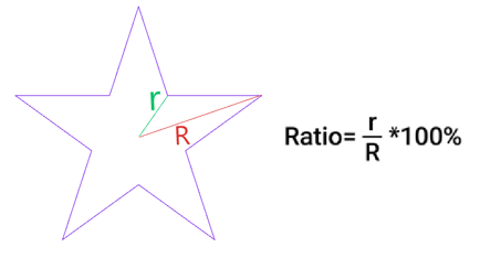
The Star ratio determines the depth of the inner vertices relative to the outer ones, serving as the primary parameter for controlling the "sharpness" or "fullness" of the shape.
-
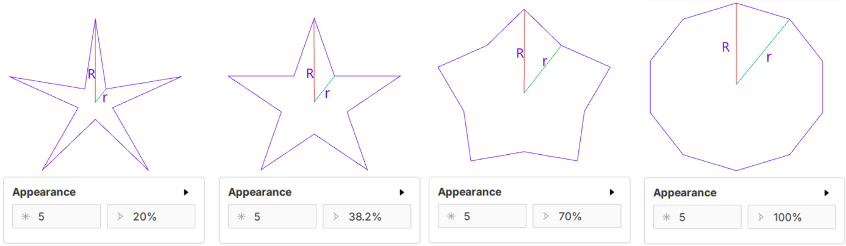
Parameter Logic: This value represents the ratio between the inner radius (r) and the outer radius (R), expressed as a percentage ().
-
Operation Instructions: Adjust the percentage within the Appearance panel. The range is 1% to 100%.
-
Application Effects:
- Ultra-low Ratio (e.g., 20%): Produces extremely sharp, elongated points, typically used for glimmer effects or radial accents.
- Standard Ratio (e.g., 38.2%): Achieves the classic "Golden Ratio" five-pointed star aesthetic.
- High Ratio (e.g., 70%): Results in a fuller, rounded appearance, resembling gears or floral outlines.
- 100% Ratio: The inner radius equals the outer radius, effectively converting the star into a regular polygon.
¶ 3.4 Corner Rounding Tool
When a rectangle, polygon, or star is selected, the top toolbar will display the Corner Rounding tool, allowing you to adjust the smoothness of the shape’s edges for softer or more decorative results.
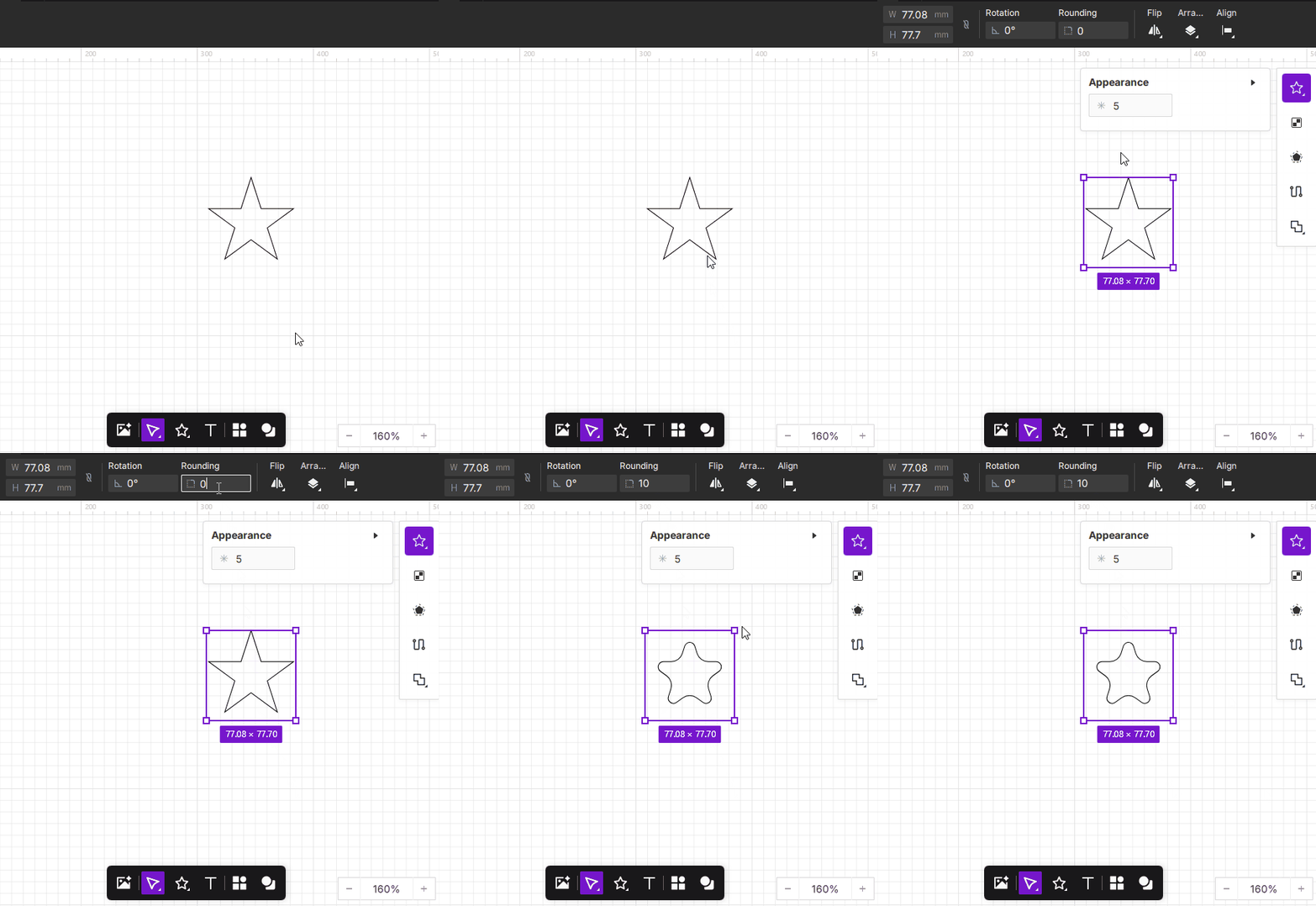
Increasing the rounding value results in smoother edges. If the value exceeds the shape’s geometric limits, the system will automatically apply the maximum allowable value.
¶ 4. Text Tool
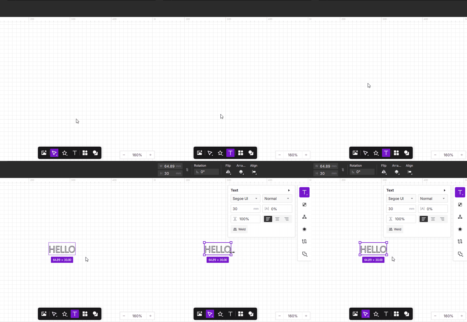
Click the  icon to add and edit text on your canvas. After selecting the tool, click anywhere on the canvas to start typing. You can then adjust the font, size, and other text properties using the Object Editing tools.
¶ 5. Tool Library
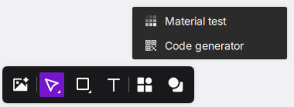
The Tool Library includes Code Generator and Material Test tools.
¶ 5.1 Code Generator
You can create functional Barcode and QR Codes directly in the software, ready for engraving. The generated codes are vector graphics, meaning they can be scaled freely without losing quality.
How to use:
- Click the
 icon to open the Tool Library, then select Code Generator.
 - In the pop-up window, choose whether you want to generate a Barcode or a QR code from the dropdown list.
- Enter the text or numeric content you want to encode.
- Click OK, and the system will generate the corresponding graphic and place it on the canvas.
¶ 5.1.1 Generating a Barcode
¶ 5.1.2 Generating a QR Code
¶ 5.2 Material Test
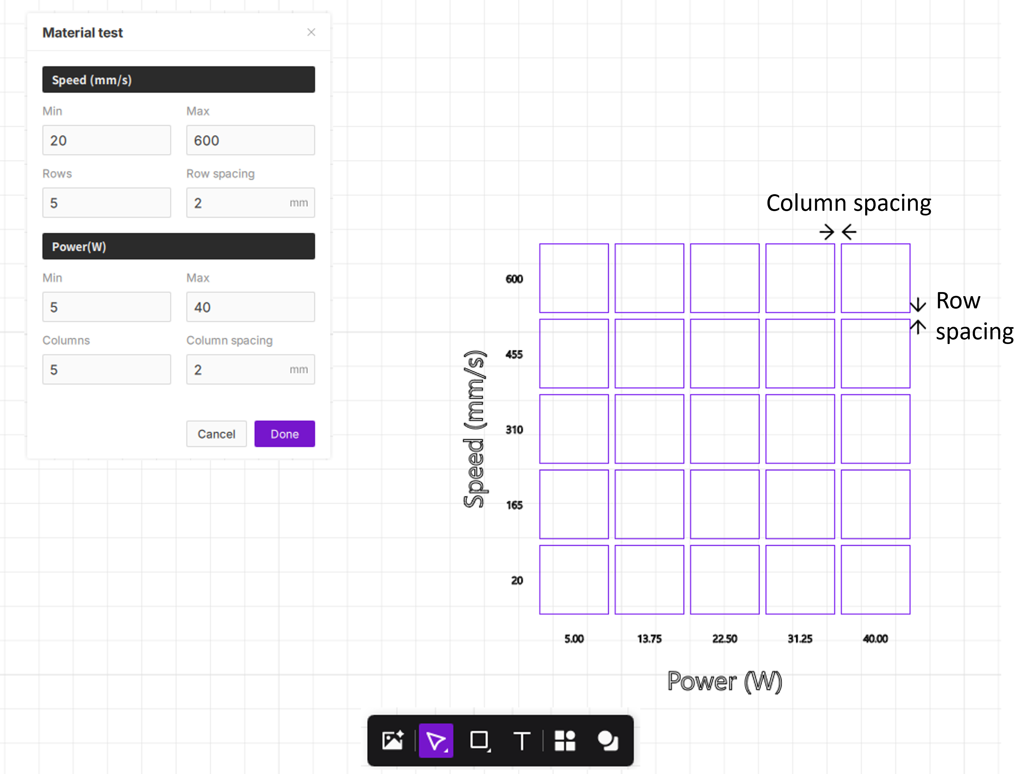
The Material Test tool helps you quickly identify the best processing parameters (such as speed and power) for your material. Based on your settings, it automatically generates a parameter matrix (Speed × Power) and displays it as a grid of test squares on the canvas. Each square represents a different parameter combination, allowing you to compare results after engraving.
You can view the article → How to Design and Perform a Material Test?
¶ 5.2.1 Purpose of Material Testing
- Quickly evaluate how different speeds and power levels affect processing results
- Avoid guesswork and save both time and material
- Identify optimal settings for challenging materials (e.g., wood, leather, cardboard, acrylic)
- Explore suitable settings when using a new material for the first time
¶ 5.2.2 How to Use
Steps:
- Create a shape on the canvas that you want to use for testing.
- Select the object and choose the processing type (Cut or Engrave) in the right-side parameter panel.
-
Click the Tool Library
icon and select Material Test. -
In the pop-up window, the system will read the selected object’s size and allow you to set your test parameters. Enter the minimum and maximum values for speed and power, as well as the number of rows and columns you want to generate (see parameter descriptions below).
-
Click Done to automatically generate a material test matrix on the canvas, complete with axis labels. You can view each test block’s parameters in the left-side parameter panel.
- After setup is complete, click Start Job to run the test and compare the final results.
¶ 5.2.3 Parameter Explanation
In the Material Test popup, parameters define the scale and value range of the generated matrix.
-
Speed (mm/s) – Vertical Axis (Y-axis) of the Matrix
- Min/Max: Sets the speed range for testing. The bottom row of the matrix will use the minimum speed, while the top row will use the maximum speed.
- Rows: Determines how many test blocks are generated vertically. More rows create a finer gradient of speed variation.
- Row Spacing: The vertical distance between each test block.
-
Power (W or %) – Horizontal Axis (X-axis) of the Matrix
- Min/Max: Sets the power range for testing. The leftmost column will use the minimum power, and the rightmost column will use the maximum power.
- Columns: Determines how many test blocks are generated horizontally. More columns create a finer gradient of power variation.
- Column Spacing: The horizontal distance between each test block.
¶ 6. Library
The Library is a built-in collection of ready-to-use vector graphics designed by professionals. It allows you to quickly add common shapes, icons, and decorative elements to your projects without starting from scratch. All assets are in SVG format, meaning they can be scaled to any size without losing quality and are fully editable.
- Click the
 icon to open the built-in Library.
¶ 7. Pen
Used to draw smooth Bézier curve paths. By adding anchor points and adjusting handles, you can precisely outline complex shape contours, making it ideal for detailed vector modeling and design.
- Click the
 icon to enter vector drawing mode.
¶ 7.1 Pen Drawing
After entering vector editing mode, the Draw tool is selected by default (shortcut: number key 1).
While dragging an anchor point, hold the Shift key, and the anchor point will lock its movement to multiples of 45 degrees.
¶ 7.1.1 Drawing a Straight Line
Left-click on the canvas to create an anchor point. After clicking, a solid purple line follows the cursor; place the cursor where you want to draw and click the canvas again to complete a vector line containing a corner point.
Once drawing is complete, right-click to bring up the finish option and click it to complete the line, or press the Enter/ESC key to finish drawing.
¶ 7.1.2 Drawing a Curve
Left-click on the canvas to create an anchor point. After clicking, a solid purple line follows the cursor; place the cursor where you want to draw, hold down the left mouse button without releasing, and drag the mouse. While keeping the left button held, slide the mouse to operate the handle, allowing you to precisely control the curve by dragging.
Once drawing is complete, right-click to bring up the finish option and click it to complete the line, or press the Enter/ESC key to finish drawing.
¶ 7.2 Node Edit
Directly manipulate the anchor points and handles on a path to make precise adjustments to a vector graphic. Suitable for scenarios such as refining contours, optimizing engraving paths, and simplifying redundant nodes. (Shortcut: number key 2)
Double-click a vector graphic to enter Node Edit mode.
¶ 7.2.1 Sharp Corner
By converting a node to the sharp corner type, the path forms a hard corner of varying degrees at that point.
After selecting an anchor point, click the  icon, then choose the
  sub-option icon.
¶ 7.2.2 Perfect Symmetric
A curved, symmetric node type in which the direction handles on both sides are equal in length and collinear in direction. Adjusting either side updates the other side in real time.
After selecting an anchor point, click the icon, then choose the  sub-option icon. Drag its direction handle, and the curvature of the path will follow the direction and length of the handle in real time.
¶ 7.2.3 Angle Symmetric
A curved node type in which the direction handles on both sides are strictly collinear (angle-mirrored in sync), but their lengths are independent. Suitable for scenarios that require a smooth curve transition while allowing different curvatures on each side.
After selecting an anchor point, click the icon, then choose the  sub-option icon. Drag its direction handle, and the curvature of the path will follow the direction and length of the handle in real time.
¶ 7.2.4 Free
After clicking an anchor point, the direction handles on both sides are completely independent—neither their direction nor their length affects the other. Suitable for scenarios that require shaping distinctly different curve directions on each side of a node.
After selecting an anchor point, click the icon, then choose the  sub-option icon. Drag its direction handle, and the curvature of the path will follow the direction and length of the handle in real time.
¶ 7.3 Segment Edit
Double-click a vector line to enter vector editing mode, where you can adjust the vector line segments. After entering Segment Edit mode, the Curve Adjust tool is selected by default (shortcut: number key 3).
Click the  icon to enter Segment Edit mode.
¶ 7.3.1 Curve Adjust
Curve Adjust is a mode for precisely editing the paths, nodes, and control handles of a vector object, used to modify the contour shape of a graphic.
After selecting a segment, click the icon, then choose the  sub-option icon to make curve adjustments to the existing segment.
¶ 7.3.2 Straighten
The Straighten tool quickly converts a curved segment between two anchor points into a straight connection, flattening the curved path segment without having to adjust the control handles one by one.
After selecting a segment, click the icon, then choose the  sub-option icon to straighten the existing curved segment.
¶ 7.3.3 Path Move
The Path Move tool is used to drag an entire segment and move it as a whole; the segment moves along with its anchor points and reshapes the surrounding path direction in real time.
After selecting a segment, click the icon, then choose the  sub-option icon to move the existing segment.
¶ 7.4 Cut
The Cut tool is used to break or trim vector paths, helping you remove unwanted segments or break a closed path into an open path. (Shortcut: number key 4)
Click the  icon to enter the Cut tool.
¶ 7.4.1 Remove Segment
The Remove Segment tool deletes an unwanted segment from a vector path while keeping the anchor points at both ends, breaking the path into an open state at the removed location.
After selecting a segment, click the icon, then choose the  sub-option icon to remove the specified segment.
¶ 7.4.2 Break Path
Break Path is used to break a path at a specified node, separating a previously continuous or closed path at that node so it becomes an open path or is split into multiple segments. This operation does not delete any node or segment; it only severs the path's connection at the selected node.
After selecting a segment, click the icon, then choose the  sub-option icon. Click the node you want to break, and the path will break at that node—the original node separates into two overlapping endpoints while the segments on both sides remain unchanged.